CSP Configurations

1. Solar Field
The parabolic trough power plants use parabolic trough collectors as solar field to concentrate the direct solar radiation onto a tubular receiver. These collector fields supply the thermal energy to drive a steam turbine. Shams Power Plant parabolic trough solar field has 192 total loops with 4 Solar Collector Assemblies (SCAs) per loop and 12 Solar Collector Elements (SCEs) per SCA.

Components of Parabolic Trough Solar Field
- Mirrors: One of the most important components of the parabolic solar field are the mirrors due to their high reflective properties, which allow to reflect a considerable fraction of the incident radiation. Most of the common parabolic trough mirrors are silver coated glass mirrors.
- Absorber Tubes: The absorber tubes or Heat Collection Elements (HCEs) allows to absorb part of the reflected energy by the mirrors due to their high radiation absorption and low radiative heat losses. The diameter of the absorber tubes needs to be sufficient to reach a high intercept factor without being too big in order to maintain low thermal losses. The intercept factor is the ratio of the total reflected radiation to the reflected radiation that hits the absorber surface.
- Hydraulic Drives Units: The hydraulic drives units allows the movement of the solar collector assemblies to track the sun along the day. The drive unit consists of two cylinders, which are controlled by two valves, determining the direction of rotation.
- Ball Joints: The ball joints are used to connect the HTF piping from the loops to the main headers, and in the crossover piping between adjacent rows of the collectors. These connections absorb the thermal expansion of the collector tube that extends the length of the collectors, and allow the collectors to rotate from the stowed position and rotate to track the sun during operation.
- Bearing Structure: The bearing structure of a parabolic trough has the function to carry the mirrors in the right position, to give stability to the troughs and to allow an exact Sun tracking. This structure consists of a main body, which in most cases is a space frame or tube structure made out of steel. Further elements of the bearing structure are the mirror support points on the space frame structure or on special cantilever arms, the receiver supports or heat collection element (HCE) supports, the structure for the mounting to the pylons, the pylons, among them drive pylons, and foundations.
2. HTF Main Pumps
The Heat Transfer Fluid (HTF) Main Pumps circulate the thermal oil through the parabolic trough solar field allowing to maintain the pressure on the primary circuit and to heat it up and pump it to the solar steam generator.
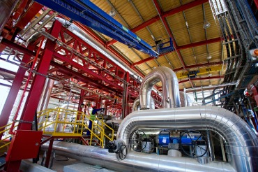
Main Characteristics of the HTF Main Pumps
- The HTF main pumps are horizontal centrifugal pumps designed to circulate thermal oil at high temperatures.
- The pumps are designed to withstand outdoor conditions.
- The pumps are equipped with variable speed drives to adapt the flow requirement for the parabolic trough solar field.
- The pumps are physically and functionally identical and are connected in parallel. One of them is installed as standby.
- The materials used for the pumps is corrosion and erosion resistant, in line with operation conditions.
3. Expansion System
The Expansion System allows to compensate the contraction and expansion of the thermal oil due to the temperature variations of the working fluid along the daily operation.
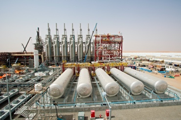
Main Characteristics of the Expansion System
- The Expansion System is composed by an Expansion Tank and several Overflow Tanks. The Expansion Tank is always located above the Overflow Tanks and in a high position.
- The Expansion System is inverted and pressurized by the use of nitrogen allowing to maintain the pressure of the thermal oil above the boiling pressure in the complete HTF system.
- The operation of the Expansion System consists:
- When the HTF level in the Expansion Tank decreases below a safety value, the overflow recirculation pumps are activated allowing to increase the level of this tank from the thermal oil stored in the Overflow Tanks. Compensation of the HTF Contraction due to a decrease of the HTF Temperature.
- When the HTF level in the Expansion Tank increases above a safety value, a dedicated valve is opened to allow storing part of the thermal oil in the Overflow Tanks. Compensation of the HTF Expansion due to an increase of the HTF Temperature.
- The venting of thermal oil vapours and nitrogen out of the Expansion and Overflow Tanks are conducted to the Ullage System.
- This system also allows the HTF make-ups by a dedicated line.
4. HTF Heaters
The Heat Transfer Fluid (HTF) Heaters are used to heat up the thermal oil when the temperature of the HTF through the parabolic trough solar field decreases below the freezing temperature and the weather conditions do not allow to increase the temperature. The main function of these HTF heaters is anti-freezing purposes, but additionally, they are also used to allow a quicker start-up of the parabolic trough solar field.
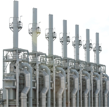
Main Characteristics of the HTF Heaters
- There are seven (7) HTF heaters installed in Shams Power Plant, which use natural gas as fuel.
- Each HTF heater has an internal recirculation in order to increase the temperature before sending the thermal oil to the parabolic trough solar field.
- The HTF heaters are foreseen to be used during operation periods or outage periods in which the weather conditions do not allow to maintain the HTF temperature in the solar field only by recirculation mode above the freezing value.
5. Steam Generator System
The steam generator system allows the generation of superheated steam by exchanging the heat provided by the thermal oil (HTF) and collected through the solar parabolic trough collectors.
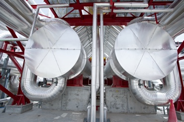
Main Characteristics of the Steam Generator System
- There are two steam generation trains installed and working in parallel at 50% load each of them.
-
Each steam generation train is composed by:
- 1 Economizer
- 1 Drum
- 2 Evaporators
- 1 Superheater
- The main characteristics of this system is to produce high pressure superheated steam and to send it to the High Pressure body of the Steam Turbine, where its first expansion is produced. HTF is used as the hot fluid.
- The Economizer heats the feed water from the Feed water Preheaters outlet temperature up to the Evaporator saturation temperature (nearly). The HTF circulates through the shell and the Water through the tubes side.
- The water to steam phase change is produced in the Evaporator and Drum being the water / steam circulating through the shell side and the HTF circulates through the tubes side in this equipment.
- The Superheater overheats the steam from the saturation temperature to the design superheated temperature and is sent to the Booster Heaters before entering into the Steam Turbine. In this case, the HTF circulates through the shell side and the steam circulates through the tubes side.
6. Booster Heaters
The Booster Heaters are the responsible of providing a higher superheating degree to the steam generated in the Steam Generation System, which allows generating electricity with a higher efficiency in comparison with a conventional parabolic trough solar power plant.
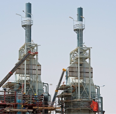
Main Characteristics of the Booster Heaters
- There are two Booster Heaters which use natural gas as fuel.
- Each Booster Heater allow to increase the steam temperature from 376 degC to 540 degC. The mass flow manages by each equipment is 50% of the total mass flow provided by the Steam Generator System.
- The main parts of each Booster Heater are:
- For the Steam, the Radiant and Convective zones.
- For the air, the combustion air preheater, which allows improving the combustion.
- The main control loop is a outlet temperature control. Additionally, the ratio air/fuel is controlled to get the maximum efficiency and lower emissions.
7. Steam Turbine
The Steam Turbine Generator unit is part of the system responsible of converting the thermal energy provided by the superheated steam into mechanical and electrical energy.
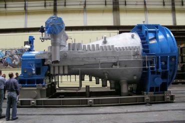
Main Characteristics of the Steam Turbine
- The Steam Turbine Generator Unit consists of:
- A Turbine High Pressure module
- A Turbine Low Pressure module
- Main Steam Connections
- Six steam bleedings
- Emergency Stop Valve
- Control Valve
- Gland Steam System
- Gland Steam System
- Lubrication oil system
- Control oil system
- Electrical Generator
- Casing
- Basic Steam Rankine Cycle.
- The Live Steam Temperature and Pressure of Shams Power Plant Steam Turbine is 540 degC and 100 bara.
- The Steam Turbine Generator and auxiliary systems has been designed and fabricated considering the operational conditions of this plant, among others, cyclic operation and quick up start-ups minimizing the time for start-up and changing operation mode.
- Maintaining the water/steam parameters within the allowable range recommended by the manufacturer is vital for the lifetime of the turbine.
- The regulation systems can be “Throttle control” or “ Sliding Pressure”.
8. Air Cooled Condenser
The Air Cooled Condenser is in charge of condensing the steam by ceding latent heat from the steam turbine exhaust steam to the fan-driver air.
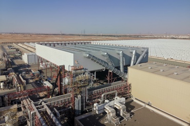
Main Characteristics of the Air Cooled Condenser
- The Air Cooled Condenser is mainly composed by:
- One steam duct including risers elements, drain pot, upper steam manifolds for distribution of the steam in the fin tube bundles, rupture discs among other components.
- Every module of the Air Cooled Condenser includes finned tube bundles, fans, motors among other components.
- ACC Drainage pumps
- Condensate Tank
- A vacuum system
- This system is designed to safely receive and condense any steam flow from the turbine, bypass system or drainage from other pipelines at high pressures.
- This dry-cooling system allows to save a considerable amount of water in comparison with a cooling tower system.